How does a timber roof support itself?
A timber roof carries loads to the building below through tied rafters, rafters supported on structural beams or engineered trusses. The outside shape does not establish which system is inside. Identify how the roof resists spread and where the main reactions go before altering rafters, ceiling joists, beams or walls.
AS 1684.4-2010 distinguishes coupled, non-coupled and trussed roofs. These are structural arrangements, not architectural styles. A gable can contain tied rafters or trusses with different joints and supports, and a flat ceiling can conceal either.
Coupled rafters rely on ties and support at the wall plates
In a coupled roof, opposing rafters meet at a ridgeboard and ceiling joists and collar ties connect rafter pairs. The low tie action helps prevent the rafter feet spreading under load. Underpurlins, where used, support the rafters between the ridge and the wall plates and carry load to struts and the supports beneath them. Part of the gravity load can therefore go to an internal support even though the rafters also sit on exterior walls.
Under AS 1684.4-2010, an underpurlin joint or lap must be over a support. Check the specific support arrangements at hips and valleys. A timber touching an underpurlin is not necessarily meant to carry its end reaction, and a neat splice does not tell you what is directly beneath it.
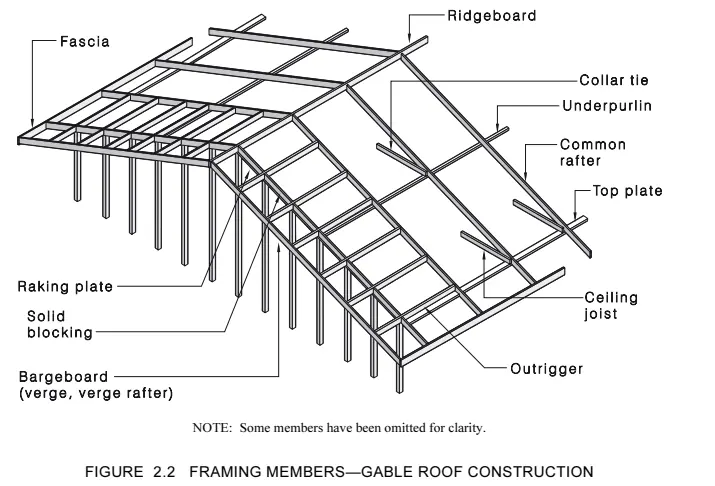
Figure 1 locates the members in a typical arrangement, not in the roof being assessed. A high collar tie and a ceiling joist tying the rafter feet act at different levels. Removing the low tie changes the force path even if the higher collar remains. Likewise, distinguish the ridgeboard in this arrangement from a structural ridge beam carrying vertical reactions.
Non-coupled rafters need a different support path
In a non-coupled roof the rafters can span to walls, a structural ridge beam or intermediate beams instead of relying on the same low tie action. A cathedral ceiling may follow the slope, exposing the members. Where a structural ridge beam is used, it needs to carry the roof and any ceiling load for which it is designed to points of support. A timber at the apex is not automatically such a beam.
Trace the beam reactions down through posts or walls and the structure beneath. Replacing a ridgeboard with a structural ridge beam can concentrate loads at its supports where the earlier roof did not impose those same reactions. Removing ties without providing a different means of support is not equivalent to making a non-coupled roof. Decide whether the new load path is feasible before work on the original system.
Trusses are assemblies with specified bearings and bracing
A truss transfers forces through its chords, webs and joints to the specified bearings. Many are designed to span without interior wall support, but that cannot be assumed from one view of the space. A girder truss can support other trusses and place larger reactions at particular points than an ordinary one. The roof's bracing and fixings are needed to keep the members in the positions assumed in design.
Use the design and layout for the actual trusses, including permanent bracing and any supports shown. A web that appears to have spare room around it is part of the truss's force path. A rule for cutting sawn rafters does not permit a change to a truss web, chord or joint. If an access route conflicts, locate a route that preserves the assembly or obtain an engineered alteration detail.
The ceiling, edges and restraint perform different jobs
Hanging beams may carry ceiling joists, while roof struts can deliver reactions to strutting beams or supporting walls. A structural fascia supports parts of an edge arrangement where specified, not every roof edge with a fascia board. The cladding loads the supporting battens and frame. Separately, connections and bracing transmit lateral forces and help hold tall beams in position. Verify which members perform both vertical and restraint functions before modifying one.
For a coupled roof with multiple rows of underpurlins, the applicable collar-tie arrangement depends on the geometry. AS 1684.4-2010 Appendix D includes arrangements for slopes of equal pitch. A high horizontal timber is not interchangeable with the low ties or the restraints required for a different roof.
Check the intersections in a roof with several wings. In a coupled arrangement the ties may not connect to every rafter at hips or through parts of a T- or L-shaped roof. A common rafter pair in a straight bay does not establish how the intersection is restrained or supported.
Check how proposed alterations change the whole system
A heavier covering increases loading, while a new opening, storage platform or removed wall may change how and where that load is carried. For example, shifting a strut sideways can bring a roof reaction to an unsupported part of a beam or wall plate. The advice should address the new reaction and the members receiving it, not only whether there appears to be room for the strut.
Use drawings and safe observations to establish the system, then verify the governing connections and bearings. A roof-space view that shows several members but not their ends may not establish where load goes. Resolve those governing details before relying on a modification or imposing additional loads.