How do bearers and joists support a timber floor?
Joists carry the flooring and deliver loads to bearers or other supports. Bearers transfer those reactions to walls, posts or stumps and ultimately the foundations. The system relies on bearing, connections and restraint at each step. It may also carry loads from walls or roof supports above, so an interior floor symptom or the size of one joist cannot establish where the problem lies. Follow the load into the framing and through its actual contacts to the ground.
What is carried by the floor frame?
Separate loads spread over flooring from concentrated loads at a wall stud or post. AS 1684.4-2010 Section 4 distinguishes joists and bearers carrying floors only from those also carrying wall or roof loads. A loadbearing wall crossing several joists can load them differently from one running along a single joist. Establish the wall's role and orientation before choosing the framing case.
At a new floor opening, a trimmer can collect reactions from the shortened joists and transfer them into side framing and connections not previously carrying them. Matching dimensions do not establish the capacity of that new arrangement.
Bearing is the loaded contact, not the nearby timber
A bearing transfers the reaction at the loaded contact. A substantial joist or bearer can still rest on too small or unreliable an area. AS 1684.4-2010 permits packing for a minor deficiency in bearer depth under stated conditions, including incompressible, corrosion-resistant material across the full support area. A wedge touching only part of the member is not equivalent.
If there is a gap or a crushed packer, establish where the load is currently being carried. A connection might restrain the member laterally without providing the vertical support the contact was meant to give. Do not drive in packing or lift the floor to test that distinction.
Where a bearer is joined, check what is continuous
Figure 1 shows different bearer support arrangements, including bearers lapped over a support. The joint sits where the support can receive reactions from both affected lengths. It does not give a repair detail for a joint in the middle of an existing span.
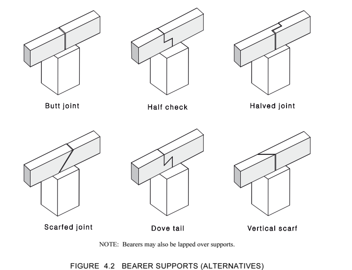
Separate lengths bearing at one support can rotate differently from a single uninterrupted member spanning over it. A visible overlap or fastener does not establish continuity for bending. Verify the joint detail; engineered products may have their own designed arrangements.
Restraint is a different job from carrying weight
Fixings can stop a bearer moving laterally on its supports, and blocking can hold joists upright. The deep-joist clauses recognise restraint both at supports and while flooring is being fixed. A deep narrow member can carry downward load as intended when restrained yet still be vulnerable to twist or roll if the restraint is absent.
The flooring distributes loads to the joists only in accordance with its own support, fixing and joint details. A sound-looking sheet does not verify the framing below it or the route into a bearer.
Relate the symptom to the framing layout
Locate bounce, a slope or a noise relative to joist direction, bearer lines, supports and changes in loading. Compare the accessible framing and alteration history. Do not jump or add load as a test.
An inspection should distinguish movement of a member under load from movement or loss of contact at a support. Where the underside is inaccessible, the interior symptom alone does not tell you which joint or member is affected.
Grain direction and support geometry affect the check
AS 1720.1 distinguishes bearing along, across and at an angle to the grain. At a bearer on a timber post, a reaction can load the bearer across its grain and the upright post along its grain. The two pieces do not have the same bearing property, even at the same contact. The assessment includes the bearing location and the dimension along the grain of the loaded member.
Effective span generally uses centres of bearing areas or connections, with a qualification for bearing longer than required. Measuring only the clear opening between supports may not describe the analytical span.
When neighbouring members can share load
The sawn-timber sharing provisions distinguish timber elements fastened to deform together from discrete parallel members connected by crossing elements or structural sheathing. The latter needs a path for loads to adjacent members if a support member fails. Counting joists is not evidence that the system meets those conditions. The sawn-timber values cannot be transferred to plywood, glulam or LVL.
Grid distribution is a separate check for concentrated or partial-area loads. The ability of crossing members to spread the load depends on their rigidity, spacing and span relative to the supporting members. A heavy load near an edge cannot be assigned equally to all joists.
In grid distribution, check where the load acts along the span and relative to the edge. Treat centre-span deflection separately under the applicable AS 1720.1-2010 method. The simple rigidity expressions assume solid sections with the stated shear allowance. Built-up I- or box-sections may need an effective rigidity that accounts for shear.
Lateral restraint and resistance to twist
A lateral restraint stops an edge moving sideways; torsional restraint resists rotation of the section. The load position and detail of the connection matter. Timber close to the beam is not by itself evidence that it can restrain it.
A separate restraint-effectiveness check is not needed in most designs. Where effectiveness is in doubt, AS 1720.1-2010 clause 1.4.4.1 calls for checking stiffness and strength. Do not disturb a restraint in service to test it.