How Are Stumps, Wall Frames and Roof Trusses Checked for Alignment?
Check a stump against vertical over its height, a wall frame against vertical or a straightedge depending on the question, and a roof truss for bow and plumbness separately. The Building and Plumbing Commission's advisory Guide to Standards and Tolerances 2026 gives different references for each check within its issuing jurisdiction. Identify the member, material, deviation and comparison rather than reporting that the frame as a whole is out of tolerance.
Distinguish lean from a local departure from straight
For a timber stump or post, section 6.1 (plumbness of timber stumps) assesses the deviation from vertical using its height. The horizontal displacement at one end has to be compared with a true vertical reference and the provision for that height, not with the slope of the site or of the floor above it. A short stump and a tall post with the same offset might therefore give different results. The vertical reference must be clear: Part B relates it to a nominated plan point or one inferred when none is nominated. A photograph taken at an angle is not the same measurement.
A post can be straight along its length and still lean. A wall frame can be vertical overall and still have a local bulge that affects a finish. These are why plumbness and straightness are separate checks. The first describes deviation from vertical; the second describes how far a surface departs locally from a straight line. Neither result can be substituted for the other.
Section 6.2 (plumbness of frames and exposed posts) distinguishes timber and light-steel frame plumbness. For straightness, section 6.3 (straightness of timber and light steel frame surfaces) specifies a 2 m straightedge for timber and a 3 m straightedge for light steel; a deviation greater than 5 mm is outside tolerance in either case. Part B does not require the stated deviation to be proportioned down for a short section. For example, the 5 mm straightness comparison is not changed to 2.5 mm merely because only half of the timber reference length is measured. Conversely, an acceptable short reading does not show that an unchecked longer section is straight. A finish may need a tighter substrate than the framing comparison alone establishes.
Truss bow uses length; truss lean uses height
Section 6.7 (roof truss bow) compares timber-truss bow with the lesser of L/200 and 50 mm, and light-steel bow with L/500. L is the truss length or distance between its supports, not the house width or apex height. Measure the deviation shown in Figure 1, not an uneven line in the roof covering. For L of 6 m, the bow comparisons are 30 mm for timber and 12 mm for light steel. Neither value identifies the cause or specifies a repair.
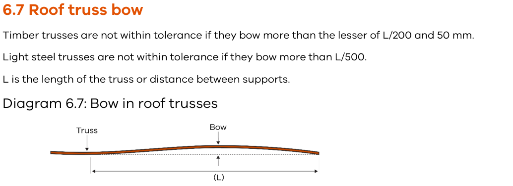
Section 6.8 (plumbness of trusses) checks whether parts of an erected truss depart from vertical, using height as the reference and separate limits for timber and light steel. A truss can lean as a plane without bowing appreciably along its length. A bowed member can also be vertical at the point checked for plumb. Report both observations separately. If it is the roof surface that looks uneven, check whether the truss, supporting frame, battens or covering accounts for it before applying a framing comparison.
Check bearing, packing and connections separately
A frame can be aligned and still lack adequate support. Sections 6.4 (packing under framing members) and section 6.5 (framing fixed to concrete slabs) address packing and proprietary bottom-plate fasteners separately. The packing enquiry includes whether the material and support are suitable and, for timber, whether its shrinkage meets the provisions for its seasoning condition. The connection enquiry includes the fastener manufacturer's installation instructions. For example, if a plate is held level on packing but locally unsupported, the level reading does not show that loads can pass into the slab as intended.
Likewise a straight, plumb wall at the edge of a slab can have a connection concern if the fastener sits too close to the concrete edge for the fixing used. One measurement concerns the plate's footprint on the concrete; the other concerns the position of the fastener. A report should distinguish them even when both can be measured in the same close-up.
Under section 6.6 (timber bottom plates that overhang concrete slabs), a timber bottom plate less than 90 mm wide must not overhang the slab; for a plate 90 mm or wider, the overhang must not exceed 10 mm. The frame and plate must not reduce the cavity below its required minimum width. Brick overhang, frame overhang and the fastener's distance from the concrete edge are three distinct dimensions. Establish which edge and material are being measured before applying a limit.
State what was measured, over what reference distance and why the provision applies. Report alignment separately from support and fastening, and identify any concealed details. Part B of the advisory guide provides a comparison method within its own scope; it does not override applicable building standards or the contract. The comparison cannot distinguish an installation departure from later deformation or establish capacity or a repair. Leave roof and subfloor access and adjustments to appropriately qualified people.